Crystal Radio Antennas

A medium wave broadcast station antenna system generally comprises a ¼ λ vertical element
and earth.

It would not be wrong to infer that such an antenna would be ideal for a crystal radio.

Crystal Radio Antenna Arrangement
However, practical reasons necessitate use of a much shorter element, with a suitable loading
coil making it resonant at the desired frequency.

Good results would be obtained with an element not shorter than 60 feet.

Related post: My first Antenna
_______________________________

Crystal Radio / Piezo Earpiece Interfacing

Here's how to interface a piezo earpiece with a crystal radio.

Parallel-tuned, series-fed radio:


The earpiece is interfaced through a 33 kΩ shunt resistor. The resistor provides a path for the
detector current. The voltage drop across the resistor drives the earpiece.

Series-tuned, shunt-fed radio:   
   

The earpiece is interfaced through a 2.5 mH RF Choke to prevent its capacitance from short-circuiting the detector. The voltage drop across the detector drives the earpiece.

Related post: Makeshift Piezo Earphones
_______________________________

Ideal detector for a Shunt-fed Crystal Radio

A Germanium transistor may be configured as a diode, having its forward voltage as low as 0.1 V, by just interconnecting its base and emitter.

Basic Shunt-fed Crystal Radio
It makes for an ideal detector in a shunt-fed crystal radio.

Related post: Crystal Radio Circuits - Alternative Concepts
_______________________________

Some thoughts on UHF Crystal Radios

Diode capacitance

Low capacitance diodes are a must for UHF crystal radios.

It follows that they are to be so wired that the capacitance between their leads is kept to a minimum.

This does not imply that the leads are to be cut to minimum length. In fact longer leads facilitate antenna-diode impedance matching.

Antenna-diode impedance matching

Stub matching is a must for maximizing the signal strength.

Dipole with a single diode
Long diode leads may be used to form the stub.

Dipole with coil and diode
A diode length of λ/4 gives a proper match.

Folded dipole
A circular stub is best for minimum capacitance between the leads.

Dipole with single-diode circular stub
Related post: UHF Crystal Radio
_______________________________

Motor problem

It was just another day at the plant.

A colleague from the neighbouring department called to say he had a problem.A replacement three phase induction motor, drawn from the stores and wired, just refused to start.

Our exchange :-

Voltage okay? 
Yes, all 3 phases terminal voltage 415V okay.

Maybe an overload or single-phasing. Does the overload relay trip?
No.

In that case it has no winding!
You crazy?!

No!
Okay, I'll check.

A little later the telephone rang again.

How did you guess?!

It turned out that someone in the motor rewinding department had sent an unwound motor back to the stores instead of a rewound one!
_______________________________

Some thoughts on shack earthing

The main purpose of mains-supply-earthing (third pin) in the shack is to blow the fuse in the event of a live-chassis fault. Protection against static build-up / lightning strike is another matter altogether.

I was a SWL in the mid-1970s and the antenna I used with a Philips transistor portable receiver was a long wire at a height of about 50 feet. One summer afternoon, the receiver front end (AF117) blew right after a loud crackle of static. 

Then again, my first tube homebrew CW rig had a 3-pin mains supply plug. The antenna was a straight dipole 50 feet high. Operating on a summer afternoon, I received a jolt through my Junker CW Key and survived to hear the crash of thunder from a nearby lightning strike. I immediately yanked the twin-line feeder and threw it on the floor (upper floor of my 2 storey house). After a few moments I was surprised to see the arc from the banana plugs to the cement floor.

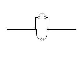
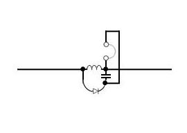
Those days, in our sparsely populated area, my antenna was way above other surrounding structures. During thunderstorms the static build-up on my 2m ¼ λ ground plane antenna would cause a whine in my 2m receiver as it dissipated through the front end coil to ground.

Conditions are totally different now, with my 2 storey house surrounded by high rises, cell phone towers and other structures with lightning arrestors. Problems of static build-up and lightning are a distant memory. I have not heard that static whine for years, even though I still use that ¼ λ ground plane antenna.

And my shack earth is just mains-supply-earth (third pin)!

Of course, if you live in the countryside, the lightning arrestor at the feeder entry-point, with a separate earth bonded to the mains-supply-earth, is a must.

While on the subject of bonding – a friend’s shack and attached bath had a separate safety earth, not bonded to the mains-supply-earth. His 2m antenna was mounted on a metal mast which was also separately earthed.

For reasons not known, the shack earth was open when the water heater developed a ground fault. The path of the fault current was through the floating earth wire, 2m rig, coax feeder braid, antenna mast and finally to ground, resulting in a coax cable fire. A parallel path also caused considerable damage to a Drake AC4 power supply.

Fortunately he had the presence of mind to pull the main breaker before he doused the fire. 
_______________________________

Rugged 807 & 1625 tubes

The good old 807 and 1625 tubes can take a real beating.

One night decades ago, when I was working DX on CW with the shack lights off, the room suddenly lit up. The cathode-keyed 807 final was white hot! I let go of the key and cut the power.

Since I was monitoring the exciter signal, I was unaware of a break in the drive and had continued to send.

After the rig had cooled and the fault rectified, it was back to normal operation again. I still have that tube.
______________________________